The electronics manufacturing industry operates under some of the tightest tolerances in the world. Components shrink with every product generation, yet the demand for traceability, compliance, and brand precision only grows. Ink fades. Labels peel. Stickers fall off in harsh environments. For manufacturers dealing in miniature parts — filter caps, ceramic substrates, PCB enclosures, and name plates — these traditional marking methods are no longer sufficient.
This blog explores why laser marking has become the industry-standard solution for electronics manufacturers who need permanent, high-precision marks on small, delicate components. From the fundamental physics of how a laser interacts with ceramic and plastic surfaces, to real-world applications in filter cap marking, 2D/3D job marking, and batch production workflows, we break down every reason why a laser marking machine for electronics has become non-negotiable on the modern production floor.
We also explore how different marking approaches — black marking versus color marking, laser versus inkjet, fiber laser versus CO2 — affect the final result. And for manufacturers ready to invest, we guide you through what to look for when selecting the right machine for your specific application, with an introduction to SLTL’s advanced laser solutions lineup built for the electronics industry.
The Marking Challenge in Electronics Manufacturing
Modern electronics components are getting smaller, denser, and more complex with each product cycle. A capacitor that once took up 5mm of board space now sits in a 0402 (1mm × 0.5mm) package. Ceramic insulators, filter caps, connectors, and microcontrollers all require unique identification — serial numbers, batch codes, QR codes, safety symbols, polarity markers, and brand logos — applied with zero tolerance for error.
Traditional marking methods struggle here. Ink-based printing smears under solvent exposure. Adhesive labels cannot survive high-temperature solder reflow processes. Mechanical engraving risks cracking delicate substrates. Pad printing lacks resolution for sub-millimeter characters.
This is the gap that laser technology fills — and it fills it permanently.
What Is Laser Marking and How Does It Work?
Laser marking is a non-contact process that uses a focused beam of light to alter the surface of a material — creating a permanent mark through oxidation, ablation, foaming, or color change depending on the material and laser parameters.
Unlike cutting, the laser in a marking application is tuned to interact with only the surface layer of the component. The beam moves across the component in precise X-Y (and sometimes Z) coordinates dictated by galvanometer-controlled mirrors, producing characters, logos, barcodes, or data matrix codes with micron-level precision.
For electronics, two primary laser types dominate:
- Fiber Lasers — Best for metals, hard polymers, and coated materials. Wavelength of 1064nm. Ideal for name plates, enclosures, and metallic components.
- CO2 Lasers — Best for ceramics, glass, and organic materials. Wavelength of 10.6μm. Widely used in ceramic capacitor and filter cap marking.
- UV Lasers — Cold processing with minimal heat-affected zones, ideal for ultra-sensitive components and plastics where thermal damage must be avoided.
To understand more about how laser marking interacts differently with ceramic and plastic substrates — and which wavelength to choose for each — see our detailed guide on How to Choose Laser Marking for Ceramic and Plastic Electronic Parts.

Why Electronics Manufacturers Prefer Laser Marking
Here is a direct answer: permanence, precision, and process compatibility.
Permanent Marks That Survive Harsh Conditions
Electronics components routinely encounter solder reflow at 260°C+, chemical cleaning agents, UV exposure, and mechanical abrasion during PCB assembly. A laser mark is not applied on top of the surface — it is the surface. It cannot be wiped off, dissolved, or peeled away.
This is critical for component traceability required under standards like IPC-7711, RoHS compliance marking, and automotive-grade TS 16949 requirements.
Sub-Millimeter Marking Precision
Modern electronics marking demands character heights as small as 0.3mm with legible resolution. Laser systems achieve this routinely. A well-configured fiber laser marking head can resolve fine-pitch data matrix codes in spaces no larger than a 3mm × 3mm square — readable by industrial vision systems for automated traceability.
For more on how precision marking impacts batch workflows, see our article on How SPM Laser Marking Improves Electronics Batch Production.
No Consumables, No Contact, No Contamination
Inkjet printers require ink cartridges, solvent maintenance, and produce waste. Pad printing pads degrade. Laser marking has no consumables — only electricity and the laser source with a rated lifespan of 50,000+ hours for fiber lasers. For a cleanroom or ESD-safe electronics production environment, no-contact laser marking also eliminates mechanical stress and contamination risk.
For a detailed side-by-side evaluation, our blog on Laser Marking vs Inkjet Printing for Electronics Components covers cost of ownership, mark quality, and production speed in depth.
Integration with Automated Production Lines
Modern laser marking machines for electronics are designed for in-line integration. They accept CAD/CAM data, connect to MES/ERP systems for real-time serialization, and can be triggered by PLCs. This makes them fully compatible with Industry 4.0 production environments.
Key Applications: Where Laser Marking Delivers Results
PCB Component Identification
Resistors, capacitors, diodes, and ICs can be marked directly with value codes, lot numbers, and polarity indicators at the component level before pick-and-place assembly.
Electronic Enclosure Marking
Laser marking on metal and plastic enclosures provides CE marks, safety warnings, serial numbers, and brand logos that comply with international certification requirements. For manufacturers who also need precise cutting of enclosure sheet metal, see our coverage on How Laser Cutting Helps Electronics Enclosure Manufacturing and our dedicated resource on . Laser Cutting Machine Selection for Electronics Sheet Metal Parts.
Name Plate Marking
Instrument panels, control boxes, and industrial electronics require durable name plates with permanent engravings. Laser marking delivers high-contrast black or color marks on anodized aluminum and stainless steel without affecting dimensional accuracy.
For a full comparison of marking styles for this application, see Color Marking vs Black Marking for Electronic Name Plates.
Ceramic Laser Marking: Precision for the Hardest Substrates
Ceramic components form the backbone of modern passive electronics — capacitors, inductors, piezo elements, substrates, and insulators are all ceramic-based. Marking on ceramics presents unique challenges:
- Hardness makes mechanical engraving impractical
- Brittleness means thermal shock from aggressive lasers can crack the part
- Surface chemistry determines whether a visible, high-contrast mark is achievable
CO2 and UV lasers are typically used for ceramic laser marking, operating with carefully tuned pulse durations and power levels that create contrast through surface oxidation rather than material removal.
The result is a permanent, high-contrast mark that survives the entire component lifecycle — including high-temperature kiln firing in some substrate manufacturing workflows.
To go deeper on material compatibility, machine specifications, and industrial use cases, read our comprehensive Ceramic Lazer Marking Machine Buyer Guide for Electronics Manufactures and our introductory piece: What Is Ceramic Laser Marking and Where Is It Used ?
Filter Cap Marking: Why Accuracy Cannot Be Compromised
Filter capacitors — used in power supply circuits, RF filters, and signal conditioning applications — are among the most marking-sensitive components in electronics. The reasons are practical:
- Tiny surface area: Filter caps are often cylindrical, with a usable marking surface measured in square millimeters
- Curved surfaces: Standard flat-field marking systems distort characters on cylindrical surfaces; accurate marking requires rotary fixtures or specialized 3D scanning heads
- Critical data: Capacitance value, voltage rating, temperature coefficient, and polarity must all be marked with zero ambiguity — misreads cause incorrect assembly
A dedicated laser marking machine for electronics configured with rotary indexing can mark hundreds of filter caps per minute with consistent character quality, no orientation errors, and repeatable depth control.
For production-scale deployments, our article on Filter Cap Laser Marking Machine for High-Volume Production covers machine configurations, throughput benchmarks, and fixture design. And for engineers evaluating marking requirements: Why Filter Cap Marking Needs Accurate Laser Marking provides the technical context.
Black and White Laser Marking for Electronics: Simple Guide
When manufacturers refer to “black marking” and “white marking,” they are describing two distinct surface interactions that a laser can produce:
Black Marking (Annealing) The laser heats the metal surface in a controlled oxidation process, producing a dark oxide layer without any material removal. The surface remains flat and smooth. Used widely on stainless steel surgical instruments and electronics name plates. Results: high-contrast black mark, corrosion resistant.
White Marking (Ablation/Foaming) The laser removes the dark surface coating (anodizing, paint, oxide layer) to reveal the bright base material below. Alternatively, on plastics, the laser creates a foamed micro-structure that scatters light and appears white or light gray. Results: high contrast against dark backgrounds, commonly used on anodized aluminum panels.
Understanding which approach to use on which substrate is critical for achieving readable, permanent marks. Our beginner-friendly guide, Black and White Laser Marking for Electronics: Simple Guide , explains both mechanisms with examples.
Laser Marking vs Inkjet Printing: A Direct Comparison
This debate comes up often in electronics manufacturing procurement. Here is a quick framework:
| Factor | Laser Marking | Inkjet Printing |
| Mark Permanence | Permanent (surface modification) | Temporary (ink layer, can fade/rub) |
| Resolution | Sub-0.1mm achievable | Typically 0.3–0.5mm minimum |
| Consumables | None | Ink, solvents, printhead replacement |
| Speed | High (scan-based) | Moderate to high |
| Material Compatibility | Metals, ceramics, plastics, composites | Porous and semi-porous surfaces best |
| Cleanroom Compatibility | Excellent (no chemicals, no aerosols) | Poor (ink mist contamination risk) |
| ROI (5+ years) | Superior (near-zero consumable cost) | Poor (ongoing ink/maintenance cost) |
For a thorough breakdown with real-world production cost modelling, read Laser Marking vs Inkjet Printing for Electronics Components.
2D and 3D Laser Marking for Complex Electronics Jobs
Most electronics marking starts in 2D — flat surfaces, flat parts, standard galvo marking heads. But modern electronics packaging increasingly involves contoured surfaces, stepped housings, cylindrical components, and multi-level assemblies.
2D Laser Marking covers standard flat-field work: PCB marking, flat name plates, labels on flat connector bodies. Fast, straightforward, and cost-effective.
3D Laser Marking uses a dynamic focusing system (z-axis control) to follow curved and uneven surfaces without distortion. This allows marking on:
- Cylindrical capacitors and inductors
- Molded plastic housings with compound curves
- Cast metal enclosures with steps and recesses
The SLTL X5 machine is specifically engineered for 3D cutting and marking applications, bringing the capability to handle complex geometries that standard systems cannot address. For a deeper technical look at both capabilities, see .SPM Laser Marking Machine for 2D and 3D Electronics Jobs.
10. Choosing the Right Laser Marking Approach for Ceramic and Plastic Electronic Parts
Not all laser marking machines are created equal — and for electronics manufacturers working with diverse component materials, the wrong laser selection results in poor contrast, thermal damage, or unreadable marks.
Key decision variables:
Wavelength Selection
- Fiber laser (1064nm): Optimal for metals, hard plastics, FR4 PCBs
- CO2 laser (10,600nm): Optimal for ceramics, glass, natural polymers
- UV laser (355nm): Optimal for ultra-sensitive plastics, medical electronics, fine-pitch components on organic substrates
Pulse Duration Shorter pulses (nanosecond to picosecond) reduce heat-affected zones — critical for small components that can be damaged by thermal spread.
Power and Speed Trade-offs Higher power with faster scan speed reduces dwell time. Lower power with slower speed increases depth. For surface marks on ceramics, low-power high-speed passes are typically preferred to prevent micro-cracking.
Our full buying guide, to Choose Laser Marking for Ceramic and Plastic Electronics Parts, walks through each variable with practical recommendations for common electronics applications.
11. Color Marking vs Black Marking for Electronic Name Plates
Electronic name plates — found on control panels, instrumentation housings, and industrial electronics cabinets — serve both functional and branding purposes. The marking approach determines the final aesthetic and durability outcome.
Black Marking on anodized aluminum and stainless steel creates a high-contrast, corrosion-resistant mark without removing base material. Ideal for outdoor equipment, marine electronics, and industrial environments.
Color Marking is achievable on certain metals (particularly titanium and stainless steel) through a phenomenon called thin-film optical interference. By precisely controlling laser energy and pulse parameters, the surface oxide layer grows to specific thicknesses that produce different colors — gold, blue, red, green — without any pigment.
For electronics manufacturers seeking premium differentiation in product branding or compliance-coded color systems on name plates, see our detailed breakdown of Color Marking vs Black Marking for Electronic Name Plates .
12. SLTL Laser Solutions for Electronics Manufacturers
SLTL Group offers a comprehensive range of laser solutions designed to address the full spectrum of electronics manufacturing requirements — from precision component marking to high-speed sheet metal cutting for enclosures.
Laser Marking Solutions
SPM Series — SLTL’s dedicated laser marking platform is engineered for electronics batch production, supporting 2D and 3D marking jobs, integration with rotary fixtures for cylindrical components, and direct connectivity to MES systems for real-time serialization. The SPM Series covers applications from ceramic capacitor marking to filter cap marking to name plate engraving
Future X — Most Advanced Laser Cutting Machine The Future X represents SLTL’s flagship laser cutting technology, equipped with the most advanced features available in the market. For electronics enclosure manufacturers competing on quality, speed, and precision, the Future X delivers the edge needed to outperform — with intelligent nozzle control, real-time cutting compensation, and ultra-high-speed traverse rates that dramatically reduce cycle times.
Ideal for: Precision thin sheet cutting for electronics chassis, high-mix enclosure manufacturing, manufacturers seeking competitive differentiation through technology.
Explore the Future X Advance Laser Cutting Machine →
Infinity F1 — High Power Laser Cutting Machine When production volume is the priority, the Infinity F1’s heavy-duty construction and high-power laser source handle demanding throughput requirements with consistency. Built for continuous operation in high-load production environments, the Infinity F1 is the workhorse for electronics manufacturers running two- or three-shift operations.
Ideal for: High-volume sheet metal cutting, heavy-gauge enclosure materials, 24/7 production environments.
Explore the Infinity F1 High Power Laser Cutting Machine →
IntegreX — Lower Power Laser Cutting Machine The most accessible entry point into laser cutting precision, the IntegreX is engineered for manufacturers who need to increase productivity and efficiency without the capital cost of high-power systems. For thin sheet electronics enclosures, brackets, and panels, the IntegreX delivers professional results with a smaller footprint and lower operating cost.
Ideal for: Small to mid-scale electronics enclosure manufacturing, first-time laser adopters, cost-sensitive production environments.
Explore the IntegreX Affordable Laser Cutting Machine →
X5 — 3D Laser Cutting Machine The X5 specializes in three-dimensional cutting — addressing shaped parts, tube profiles, hydroformed components, and formed sheet metal that standard 2D flatbed cutters cannot handle. For electronics manufacturers working with non-planar enclosure geometries or custom formed housings, the X5 opens new design possibilities.
Ideal for: 3D enclosure cutting, tube and profile cutting, complex formed electronics housings.
Explore the X5 3D Laser Cutting Machine →
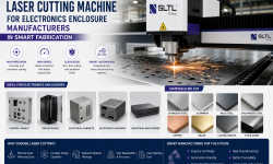
For the full picture of how SLTL’s cutting solutions serve the electronics enclosure segment, see our dedicated guide: Laser Cutting Machine for Electronics Enclosure Manufacturers.
FAQs
Q1: What type of laser marking machine is best for small electronics components?
The best laser marking machine for electronics depends on the material. For metal components and name plates, a fiber laser marking machine offers the best combination of speed, contrast, and permanence. For ceramics and sensitive polymers, a CO2 or UV laser is typically preferred due to its lower thermal impact and optimal absorption characteristics. SLTL’s SPM Series is specifically configured for electronics applications and supports multiple laser wavelength options. For a full buyer’s guide, see Best Laser Marking Machine for Electronics components and Ceramic Laser Marking Machine Buyer Guide for Electronics Manufactures
Q2: Can laser marking damage delicate electronic components?
When configured correctly, laser marking produces zero mechanical stress and minimal thermal impact. The key parameters are pulse duration, repetition rate, and power density. UV and picosecond lasers are specifically used for ultra-sensitive components because their short pulses transfer energy to the material surface before heat can spread to the bulk component. For high-volume, precision-sensitive applications such as filter caps and ceramic capacitors, proper machine selection and parameter tuning ensure mark quality without component damage.
Q3: How does laser marking improve traceability in electronics manufacturing?
Laser marking supports direct part marking (DPM) with permanent 2D data matrix codes, QR codes, and barcodes that can encode serial numbers, batch IDs, manufacturing dates, and compliance data. These marks survive the entire product lifecycle — including reflow soldering, chemical cleaning, and field service — ensuring that components remain traceable from production floor to end customer. This supports IPC, ISO, and automotive traceability standards, and integrates directly with MES/ERP systems through serialized marking workflows.
Q4: What is the difference between laser marking, laser engraving, and laser etching for electronics?
These terms are often used interchangeably but describe different surface interactions:
- Laser Marking is a broad term covering any laser-induced surface modification — including annealing, ablation, foaming, and color change.
- Laser Engraving specifically refers to material removal — the laser physically vaporizes a layer of material, creating a recessed mark. Used for deep, tactile marks on name plates and panels.
- Laser Etching involves melting the surface to create a raised or textured mark with high contrast. It is faster than engraving but shallower.
For most electronics component marking applications — where surface area is limited and thermal impact must be minimized — laser marking (annealing or ablation) is preferred over deep engraving.
Conclusion
The move toward laser marking machines for electronics is not a trend — it is a structural shift driven by the physics of miniaturization, the demands of global traceability standards, and the economics of high-volume production. Ink fades. Labels fail. Only a permanent, high-precision laser mark reliably identifies a component from the moment it is made to the moment it is disposed of.
For electronics manufacturers, the question is no longer whether to adopt laser marking, but which system to adopt and how to configure it for your specific applications — whether that is ceramic capacitor marking, filter cap marking, name plate engraving, 2D/3D job marking, or high-volume batch production.
SLTL’s comprehensive portfolio of laser marking, cutting, and welding solutions is purpose-built for the demands of electronics manufacturing — from precision marking of the smallest passive components to high-speed cutting of enclosure sheet metal. Explore our full range of solutions and find the right configuration for your production requirements.